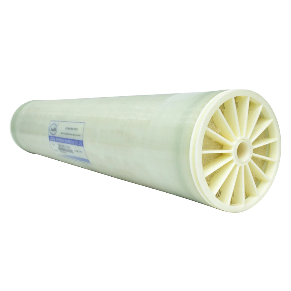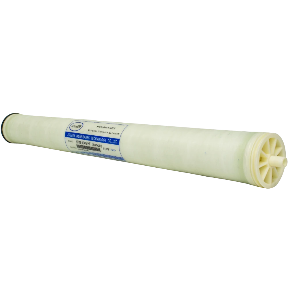
Reverse osmosis (RO) membranes are essential components in industrial water treatment systems, separating dissolved salts and other contaminants from water under pressure. Their performance depends not only on the selective membrane material but also on the supporting layers and structural components that form the complete membrane element.
Understanding RO membrane structure involves two levels: the thin film composite (TFC) membrane sheet and the spiral-wound membrane element. The first provides the selective barrier, while the second integrates membrane sheets, flow channels, and supporting components into a compact cylindrical assembly.
This guide explores the materials, layers, and components of an RO membrane, explains how spiral-wound elements are constructed, and examines how structural design influences performance.
What Is the Structure of an RO Membrane?
The structure of an RO membrane can be understood at two levels: the microscopic membrane sheet and the complete membrane element.
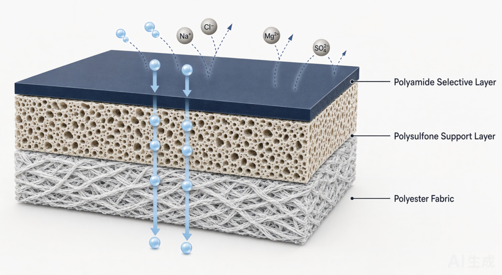
At the material level, most industrial RO membranes use thin film composite construction, typically consisting of three layers:
- Polyamide selective layer: The active surface responsible for separating water from most dissolved salts.
Porous polysulfone support layer: Provides structural support beneath the selective layer.
Nonwoven polyester fabric: Serves as the mechanical backing for the composite membrane sheet.
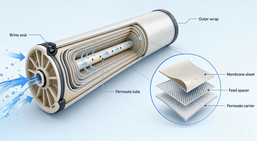
At the element level, multiple membrane sheets are combined with feed spacers and permeate carriers, then wound around a central permeate tube. Components such as anti-telescoping devices, brine seals, and an outer wrap help maintain the element’s structure and control water flow.
These two levels work together: the TFC layers perform the separation, while the spiral-wound assembly provides the flow channels and mechanical support required for operation.
The Layer Structure of a Thin Film Composite RO Membrane
Most modern industrial RO membranes use a Thin Film Composite (TFC) structure, combining materials with different properties to provide selective separation, water transport, and mechanical strength.
Polyamide Selective Layer
The polyamide selective layer is the active surface of a typical TFC RO membrane. This extremely thin, dense polymer layer is commonly formed through interfacial polymerization. It allows water to pass under applied pressure while rejecting most dissolved salts and many other dissolved substances.
Its chemical composition, surface characteristics, thickness, and integrity influence membrane selectivity and permeability. Oxidation or physical damage can compromise this layer, potentially increasing salt passage and reducing separation performance.
Porous Polysulfone Support Layer
Beneath the polyamide layer is a porous polysulfone support. Its open structure allows water to move toward and through the selective layer while providing the mechanical support needed to maintain membrane integrity.
The support layer must balance porosity and strength. It should support the thin active layer and withstand operating pressure without creating unnecessary resistance to water transport.
Nonwoven Polyester Fabric Support
The bottom layer is typically a nonwoven polyester fabric, approximately 120–150 microns thick. This backing provides mechanical strength, tear resistance, and dimensional stability, helping the membrane maintain its structure during manufacturing, element rolling, and operation.
Although it does not perform the primary separation function, the polyester backing is essential to the durability and handling of the composite membrane sheet.
How the Three Layers Work Together
Each layer has a distinct role within the composite structure:
|
Layer |
Main Function |
|
Polyamide selective layer |
Controls selective separation and salt rejection |
|
Polysulfone support layer |
Provides porous structural support and water transport |
|
Polyester backing |
Adds mechanical strength and dimensional stability |
Together, these materials form a composite membrane sheet that balances separation performance with mechanical durability. The quality and consistency of each layer contribute to the reliability of the finished RO membrane.
Key RO Membrane Material Selection
RO membrane material selection must consider the different functions of each layer. Polyamide provides selective separation, polysulfone supports the active layer while allowing water transport, and polyester provides mechanical backing.
Material purity, porosity, chemical compatibility, and structural consistency can all influence membrane quality. For industrial applications, selection should also account for feed-water composition, operating pressure, temperature, and the chemicals used during membrane cleaning.
Main Components of a Spiral Wound RO Membrane Element
A spiral wound reverse osmosis membrane element combines membrane sheets with several supporting components to create a compact structure with a large effective membrane area. Each component contributes to feed-water distribution, permeate collection, sealing, or mechanical stability.
RO Membrane Sheet
The membrane sheet is the primary separation component. During manufacturing, it is folded into a membrane leaf with a permeate carrier positioned between its two membrane surfaces. The edges are sealed, typically using polyurethane adhesive, to form a permeate collection channel connected to the central tube.
Multiple membrane leaves are then assembled into the spiral-wound element.
Feed Spacer
The feed spacer is a synthetic mesh positioned between adjacent membrane leaves. Commonly around 28–40 mil thick, it creates open channels for feed water to flow along the membrane surfaces.
Its mesh structure promotes mixing, helps reduce concentration polarization, and supports water distribution through the element. Spacer geometry also influences hydraulic resistance, pressure drop, and the potential for deposit accumulation.
Permeate Carrier
The permeate carrier is a porous, often knitted fabric positioned inside the membrane leaf. It creates a collection channel for water that passes through the membrane and directs it toward the central permeate tube.
Its structure also supports the membrane envelope against compaction under operating pressure. Adequate permeability and structural stability are important for efficient permeate collection.
Permeate Tube
The central permeate tube collects water from the membrane leaves and conveys it toward the element outlet. It is typically manufactured from rigid engineering plastics such as PVC, ABS, or Noryl, with openings that allow permeate to enter from the surrounding membrane leaves.
The tube must maintain structural strength while providing a reliable collection pathway.
Anti-Telescoping Device and Outer Wrap
Anti-Telescoping Devices (ATDs) are rigid end components installed at both ends of the element. They help prevent membrane leaves from shifting axially under differential pressure forces, maintaining the stability of the wound assembly.
The outer wrap surrounds the cylindrical membrane assembly, holding the wound layers together and providing mechanical protection. Depending on the element design, it may use a high-strength fiberglass shell or tape wrapping.
Brine Seal and Other Sealing Components
The brine seal is a flexible U-cup ring typically fitted near the feed end of the element. It helps prevent feed water from bypassing the membrane through the gap between the element and the pressure vessel wall, directing it through the intended feed channels.
Interconnectors and O-rings connect the central permeate tubes of adjacent elements inside a pressure vessel. These seals help maintain separation between the feed-side and permeate-side flow paths and prevent leakage between connections.
Understanding the Spiral Wound RO Membrane Structure
The spiral-wound configuration combines a large membrane surface area with a compact cylindrical design. It is widely used in industrial RO systems because multiple membrane leaves and flow channels can be arranged around a central permeate tube.
How Membrane Sheets Are Arranged
A membrane sheet is folded with a permeate carrier between its two active surfaces to form a membrane leaf. The leaf edges are sealed to create an internal permeate channel, with a connection to the central permeate tube.
Feed spacers are positioned between adjacent leaves, creating channels through which feed water flows. This arrangement keeps the feed-water pathway separate from the internal permeate collection channel.
How the Membrane Element Is Rolled
Multiple membrane leaves are connected to the central permeate tube and wound around it to form a cylindrical assembly. Feed spacers maintain the required flow channels between leaves, while the permeate carriers provide pathways for collecting water that passes through the membrane.
After winding, the assembly is secured with an outer wrap and fitted with the necessary end components and seals. This construction allows a substantial membrane surface area to fit inside a standard pressure vessel.
Feed Water, Permeate, and Concentrate Flow Paths
The spiral-wound structure separates water into three main flow paths:
- Feed Water: Enters the element and flows axially through the channels formed by the feed spacers. Part of the water passes through the membrane surfaces under pressure.
- Permeate: Passes through the selective layers, enters the permeate carriers inside the membrane leaves, and flows toward the central permeate tube for collection.
- Concentrate: The remaining feed water continues through the feed channels with an increased dissolved-solids concentration and exits the element as concentrate.
The correct arrangement and sealing of membrane sheets, spacers, permeate carriers, and the central tube are essential to maintaining these separate flow paths.
How RO Membrane Structure Affects Performance
RO membrane structure influences separation efficiency, hydraulic behavior, and mechanical reliability. Both the properties of the composite membrane layers and the design of the complete element contribute to operating performance.
Selective Layer and Salt Rejection
The polyamide selective layer is the primary barrier responsible for salt rejection. Its chemical properties and structural integrity influence the balance between water permeability and dissolved-solids rejection.
Defects, oxidation, or physical damage can compromise the layer and increase salt passage, making consistent material quality and manufacturing control essential.
Feed Spacer and Pressure Drop
Feed spacer geometry affects flow distribution, mixing, and hydraulic resistance within the element. A suitable design helps reduce concentration polarization, but spacer thickness and mesh configuration also influence pressure drop and the potential for fouling.
Effective RO membrane element design must balance adequate feed-channel mixing with acceptable pressure losses.
Permeate Carrier and Water Collection
The permeate carrier provides the internal pathway for collecting water after it passes through the membrane. Its porosity, thickness, and structural consistency influence flow resistance and the efficiency of water transport toward the central tube.
A properly designed permeate channel helps maintain effective water collection throughout the membrane element.
Element Geometry and Mechanical Stability
The overall geometry of a spiral-wound element determines how membrane area and flow channels are arranged within the pressure vessel. The membrane leaves, central tube, feed spacers, ATDs, outer wrap, and sealing components must function as an integrated assembly.
Accurate component positioning and reliable sealing help maintain the intended water pathways, while mechanical stability allows the element to withstand operating pressure and associated hydraulic forces.
Good RO membrane element design therefore requires a balance between membrane area, flow-channel configuration, pressure drop, sealing reliability, and structural durability.
Conclusion: Understanding RO Membrane Structure and Design
RO membrane structure consists of two interconnected levels: the TFC membrane sheet and the complete spiral-wound element. The polyamide selective layer, polysulfone support, and polyester backing form the composite membrane, while feed spacers, permeate carriers, central tubes, and sealing components create a functional membrane element.
Each material and component contributes to separation, water flow management, or mechanical stability. Understanding these structural relationships helps water treatment professionals evaluate membrane construction and select suitable elements for industrial applications.
JOZZON develops and manufactures membrane solutions for diverse industrial water treatment requirements. Contact our engineering team to discuss your feed-water conditions, system design, and RO membrane selection needs.