1. Single-component system
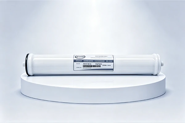
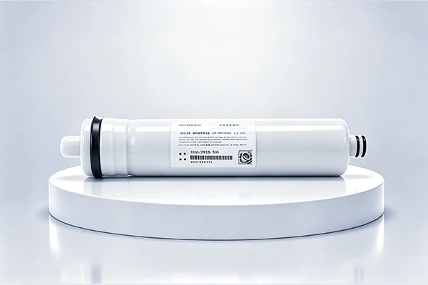
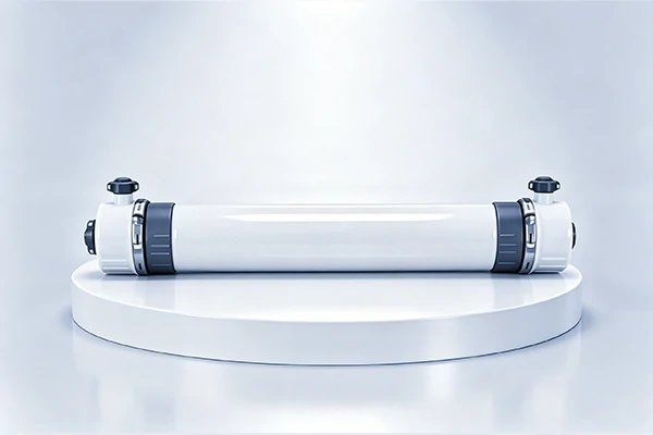
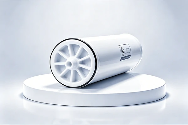
The assembly consisting of membrane elements housed within a pressure housing is called a membrane module. Currently, large-scale water treatment systems typically use pressure housings that can connect to several standard 40-inch membrane elements. The concentrate from the first membrane element becomes the feed water for the second element, and so on. The permeate pipes of all membrane elements are interconnected and connected to the permeate interface on the end plate of the module’s pressure housing. The permeate outlet of the module can be selected at either the inlet or concentrate end of the module.
When a system contains only one or a few membrane elements, it is called a single-module system. Although the number of membrane elements is small, the supporting equipment is complete. Therefore, familiarity with single-module systems is a prerequisite for understanding the design of large systems.
(1) Single-component system:
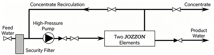
Raw water entering the membrane system passes through a shut-off valve, first flowing through a security filter, then into a high-pressure pump. After being pressurized, it enters the inlet of the membrane module. When the permeate leaves the membrane module, the permeate pressure should not be too high to prevent damage to the membrane element due to back pressure. However, in reality, a certain permeate pressure is often required, for example, when the permeate needs to be transported to a post-treatment section or supplied to a point of use. A high-pressure pump must be added to supplement the pressure required for downstream permeate delivery. However, it is crucial that the outlet pressure of the high-pressure pump does not exceed the maximum allowable inlet pressure of the membrane element, and particularly effective measures should be taken to ensure that the permeate pressure does not exceed the inlet pressure at any time (even momentarily).
The pressure of the concentrate leaving the component’s concentrate outlet is similar to the inlet pressure. The pressure difference between the inlet and concentrate outlet in the system is typically between 0.3 and 2 bar, depending on the component’s performance, quantity, flow rate, and water temperature. The concentrate control valve controls the concentrate flow rate and the system’s recovery rate, which must not exceed the design specifications.
In single-module systems, concentrate recirculation is often required to meet design requirements for module recovery rates. A small portion of the concentrate leaving the module is discharged, while the majority flows back into the suction port of the high-pressure pump. This increases the flow rate within the module. A high proportion of concentrate recirculation can help reduce the module recovery rate and lower the risk of membrane fouling. However, it also has the following disadvantages:
- The quality of the produced water will also decrease accordingly.
- Larger high-pressure pumps are needed, resulting in higher energy consumption and increased costs.
- After the system is cleaned or shut down and then restarted, the rinsing process may take a long time.
2. Single-segment system
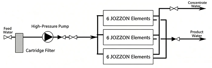
In a single-stage system, membrane modules are connected in parallel, with the feed water, product water, and concentrate each connected separately via a main piping system. Single-stage systems are typically used when a system recovery rate of less than 50% is required. To improve the recovery rate, more membrane elements can be connected in series within each pressure vessel.
3. Multi-segment system
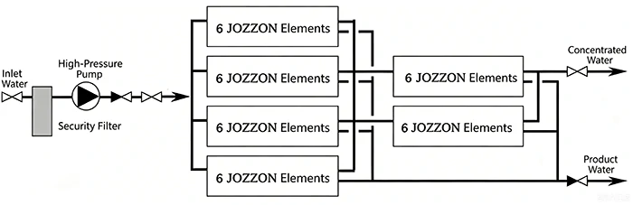
When higher system recovery rates are required, multi-stage systems are used without exceeding the recovery rate limit of a single membrane element. A two-stage system typically achieves a 75% system recovery rate, calculated based on each stage using a module with six membrane elements. Generally, the higher the system recovery rate, the more membrane elements must be connected in series. To balance the continuous diversion of permeate and maintain uniform feed water flow within each stage, the number of pressure vessels in each stage decreases in the direction of feed water flow. A typical arrangement ratio is 2:1, defined as the ratio of the number of pressure vessels in two adjacent stages. The following diagram shows a two-stage system with a 4:2 arrangement:
Conventional RO/NF systems for water desalination typically employ a single-pass feedwater design. In this design, the feedwater flows through the membrane system only once. A portion of the feedwater permeates through the membrane surface to become product water, while the remaining feedwater is continuously concentrated and leaves the system at a higher concentration.
When the number of components is too small to achieve sufficient recovery rates, a concentrate recirculation system can be used. Concentrate recirculation systems are widely used in specific applications, such as process material concentration and wastewater treatment. In some systems with internal concentrate recirculation, a portion of the concentrate is directly returned to the inlet of that section and mixed with the feed water. In multi-stage systems, each section can be equipped with a separate concentrate recirculation pump. The figure below shows a concentrate recirculation system designed as a single-pass feed water system.
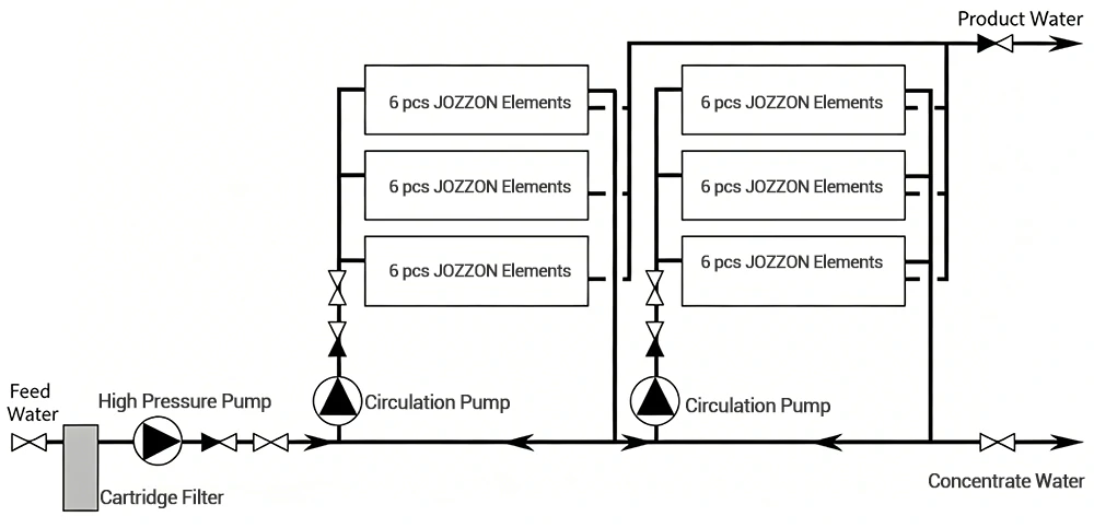
The main advantage of concentrate recirculation is that the feed water flow rate within the membrane module can be kept constant, unaffected by changes in the fouling level of the upstream membrane module or the composition of the feed water.
When selecting a circulating water pump, a small portion of the concentrate leaving the current stage can be recirculated while the majority enters the next stage. This makes the system close to a one-pass operation mode, but still retains the advantage of recirculation.
4. Multilevel System
In some projects, single-stage systems cannot meet water quality requirements; ion exchange is not permitted as a post-treatment method; the removal of viruses, bacteria, pyrogens, and organic matter is particularly important; or higher system reliability is required, in which case multi-stage membrane treatment systems can be designed, such as in pharmaceutical and medical manufacturing processes.
A multi-stage membrane treatment system is actually a combination of multiple traditional RO/NF systems. The product water from the previous stage is used as the feed water for the next stage. The two stages can be single-stage or multi-stage, and can be either single-pass or concentrate recirculation mode.
The concentrate from the second stage can be returned to the inlet of the first stage because its quality is still better than the raw water entering the system. Therefore, the system has a higher water recovery rate and can use fewer membrane elements.
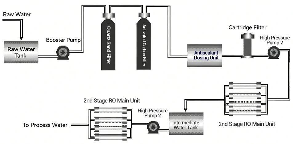
Two-stage reverse osmosis system
As long as the maximum allowable feedwater pressure of the membrane element is not exceeded, the entire system can be equipped with only one high-pressure pump, without the need for a separate pump for each stage. The second stage is driven by the permeate pressure of the first stage. However, at any time, the difference between the permeate pressure and the feedwater or concentrate pressure of the same stage (i.e., back pressure) must not exceed 0.3 bar. Alternatively, an intermediate transition tank can be set up to collect the permeate from the first stage, and then the high-pressure pump can be used to supply water to the second-stage reverse osmosis unit. This method can effectively solve the problem of balancing the treatment capacity of the first and second-stage RO system.
In most cases, the conductivity of the permeate is the most important parameter for permeate quality. Since CO2 cannot be removed by the membrane, it will remain in the finished product water, forming carbonic acid and causing an increase in conductivity. By adjusting the ph of the feed water to around 8.2 with alkali, CO2 can be prevented from passing through the reverse osmosis membrane. Under this ph condition, all CO2 will be converted into carbonic acid, which can be effectively removed by the membrane. NaOH can be added to either the primary feed water or the permeate water. When adding NaOH to the permeate water, special attention should be paid to the amount added to prevent excessive ph adjustment. In addition, calcium carbonate precipitation should be prevented.
5. Special Design
For specific requirements, several special designs are available:
- Improve product quality:
Under brackish water source conditions, seawater components are selected; the final stage of produced water is returned to the influent.
- Improve the system’s recovery rate:
Use the concentrate as feed water for the second system, i.e., add a concentrate recovery system; install inter-stage booster pumps between stages to offset the increase in osmotic pressure in the downstream stage; and use JSW membrane elements in the first stage.
- Reserve the opportunity for future system upgrades:
Blank elements are used in pressure vessels; the membrane module support adopts a modular design.
- We can design a suitable membrane treatment system according to the customer’s needs.