1. Introduction
Proper system operation and maintenance are crucial for ensuring the long-term high-performance and stable operation of RO and NF membrane systems. This includes initial system commissioning and daily start-up and shutdown procedures, as well as the prevention of membrane element fouling, scaling, clogging, oxidative degradation, and hydraulic shock damage. These aspects should be fully considered not only during the design phase but also during manufacturing, installation, commissioning, operator training, and daily operation management. Operational records must be maintained and data standardized to promptly understand the actual system performance and take immediate corrective action when necessary. Complete and accurate records are also required when requesting system performance guarantees.
2. Initial Start-up Inspection
Before the membrane system is put into operation for the first time, pretreatment checks, membrane element installation, instrument calibration, and other inspections must be carried out.
After the membrane element is installed, before starting the membrane unit, it should be ensured that the pretreated effluent meets the requirements specified for RO membrane feed water, and all indicators such as temperature, conductivity, and flow rate must be stable and qualified.
Things to check before powering on:
- All equipment, including pipelines, containers, instruments, and pumps, are made of materials that meet the usage requirements.
- The multi-media filter , ultrafiltration and other pretreatment equipment have been cleaned and the effluent is qualified;
- A safety filter was installed on the upstream pipeline of the high-pressure pump , and the water produced was qualified after commissioning .
- The chemical dosing point is located correctly;
- If oxidants such as chlorine are used, there should be reliable measures to ensure that the chlorine in the feed water is completely removed before the membrane system is used.
- Measures have been taken to ensure that the product water pressure does not exceed the inlet water or concentrate pressure;
- It can sample the total influent, influent, product water, concentrate, and total product water of the system;
- Avoid subjecting membrane elements to extreme temperature conditions, such as storing them in freezing areas, direct sunlight, or near heating vents;
- Each water pump is ready for operation, the couplings are properly aligned, adequately lubricated, and can rotate easily and freely;
- Product water and concentrate should be discharged directly and reuse is strictly prohibited .
3. Initial Startup Sequence
To prevent membrane damage caused by excessive feed water flow and pressure, the reverse osmosis system must be started up properly. Following the correct startup sequence is essential to ensure that the system’s permeate water quality and quantity meet design targets.
Before starting the system, pretreatment commissioning, membrane element loading, instrument calibration, and other system checks should be completed. Taking the typical membrane water treatment system shown in the figure below as an example, the recommended general startup sequence is as follows:
(1) Before the system is started , first, ensure that the raw water does not enter the membrane element, thoroughly flush the raw water pretreatment section to remove impurities and other pollutants, check whether the pretreated effluent is qualified, and whether the influent contains residual chlorine or other oxidants, until the pretreated effluent is qualified.
(2) Check that all valves are flexible and ensure that all valves are kept open or closed as designed.
Fill the membrane element and pressure vessel with low-pressure ( flushing pressure is 0.2~0.4MPa , it is recommended to control the flushing pressure at 0.2-0.3MPa for the first 2 hours to facilitate the discharge of air from the dead end of the membrane element ) feed water. The flushing flow rate for each 4-inch pressure vessel is 0.6~3.0 m3/h, and the flushing flow rate for each 8-inch pressure vessel is 2.4~12.0 m3/h. Control the feed water flow rate of the membrane system to be less than 50% of the operating feed water flow rate. All permeate and concentrate during the flushing process should be discharged and not reused .
(4) During the water flushing operation, carefully check all valves and pipes for leaks and tighten or repair them.
(5) Systems with wet membranes should be flushed for at least 30 minutes. Systems with dry membranes should be continuously flushed at low pressure for at least 6 hours, or initially continuously flushed at low pressure for at least 3 hours, soaked for 8 hours, and then continuously flushed at low pressure for 2 hours . During low-pressure, low-flow flushing and soaking, scale inhibitors and other agents are not allowed to be added to the pretreatment section. For systems with dry membranes, our company recommends the first option.
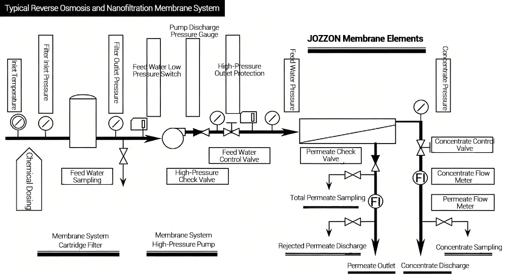
Typical system diagram
(6) Reconfirm that the product water valve (not shown in the figure ) and the concentrate control valve are in the open position.
(7) When starting the high-pressure pump for the first time, the inlet control valve between the high-pressure pump and the membrane element must be in a state of near full closure to prevent the impact of water flow and water pressure on the membrane element. At this time, the starting current of the high-pressure pump is also the smallest, and the impact on the power grid is low.
(8) Start the high-pressure pump.
(9) It is very important to avoid excessive flow and pressure impact on the membrane system. Therefore, after the high-pressure pump is started, the high-pressure pump outlet inlet control valve should be opened slowly to uniformly increase the inlet flow rate to the design value. The pressure increase rate should be less than 0.07 MPa per second .
(10) While slowly opening the high-pressure pump outlet inlet control valve, slowly close the concentrate control valve to maintain the concentrate discharge flow rate specified in the system design. At the same time, observe the system product water flow rate until the product water flow rate reaches the system design value. In this way, the system recovery rate will not exceed the design value. Check the system operating pressure to ensure that it does not exceed the design upper limit.
(11) Check whether the dosage of all chemical agents is consistent with the design value, such as acid, scale inhibitor and sodium metabisulfite (sodium bisulfite), and measure the ph value of the influent (the dosage of scale inhibitor can exceed the standard by 30% within the first 4 days of initial operation, and the standard dosage shall be restored after the system is stable) .
(12) Check the Langerier Saturation Index (LSI) or Stevie-David Stability Index (S&DSI) of the concentrate , which are obtained by measuring the ph , conductivity, calcium hardness and alkalinity of the concentrate and by appropriate calculation.
(13) Test the conductivity of the water produced by each pressure vessel, analyze whether there are any pressure vessels that do not meet the expected performance, and determine whether there is leakage or other faults in the membrane element and the pressure vessel “O” ring.
(14) Confirm that the safety devices of the machinery and instruments are operating properly.
(15) After the system runs continuously for 1-2 hours until the produced water is qualified, open the produced water delivery valve and then close the produced water discharge valve to start producing water.
(16) Record all operating parameters once per hour.
(17) After running continuously for 24-48 hours, view all recorded system performance data. At this time, the system operating parameters serve as the benchmark for system performance.
4. Daily Startup
After a membrane system is put into operation, it often starts and stops frequently due to various objective reasons. Each start-up and shutdown can cause sudden changes in system pressure and flow, affecting the membrane elements. Therefore, the number of system starts and shutdowns should be minimized, and normal start-up and shutdown processes should be as smooth as possible. The start-up method should, in principle, be the same as the initial start-up procedure . When shutting down, the system must be effectively flushed with reverse osmosis product water at low pressure, and scale inhibitors or other chemicals should not be added during this process .
The daily startup sequence can be automatically achieved by the programmable logic controller and remote control valve, but it is necessary to periodically calibrate the instruments (as the instruments are used for a long time, data drift and inaccuracy may occur), and check that the alarms and safety protection devices are in the correct working condition.
Note: When customers use our products, our staff is responsible for informing them of the above operating steps and precautions in advance and confirming that they have fully understood them. If our staff has clearly informed customers of the above operating steps and precautions and explained their importance, but the customer fails to effectively implement them on-site due to reasons such as lack of available conditions, the customer shall make their own judgment and bear the relevant responsibilities . Our company shall not bear any responsibility for any consequences arising therefrom .
5. Operation Log
All system-related data must be collected, recorded, and archived for traceability. Running data logs is also an effective tool for identifying and troubleshooting. Generally, the following items need to be recorded or calculated:
Power-on Report
(1) The flow chart is used to represent the water source, pretreatment system, RO/NF system arrangement and posttreatment system, providing an intuitive and comprehensive introduction to the RO/NF system.
(2) Record the results of each of the pre-start checks listed above.
(3) Provide calibration curves for various instruments according to the manufacturer’s recommendations.
Recording of Preprocessing Operation Parameters
Since the performance of an RO/NF system largely depends on the rationality of pretreatment operations, the operating characteristics of pretreatment equipment must be recorded. Because pretreatment processes vary from place to place, a standardized recording form cannot be provided. Generally, the following items should be recorded:
(1) Record the total residual chlorine concentration in the influent every day.
(2) Record the pressure drop of all pretreatment filters daily.
(3) Calibrate all instruments at least every 3 months according to the manufacturer’s recommended method.
Membrane operating parameter recording
The following parameters need to be monitored and recorded on a suitable record sheet (as shown in the table below), at least once per shift.
(1) Operation date, time and system uptime.
(2) Pressure drop across the security filter and each section of the pressure vessel (membrane module).
(3) The parameters of each influent, product water and concentrate, including pressure, temperature, flow rate, ph value, SDI value, turbidity value and conductivity.
(4) Average concentration of influent. This includes calculation methods such as arithmetic mean and logarithmic mean.
6. System Shutdown
When shutting down the membrane system, the entire system must be flushed with permeate or high-quality feed water to displace the high-salinity concentrate from the pressure vessel and membrane elements until the concentrate effluent conductivity is close to the feed water conductivity. The flushing should be carried out at a low pressure of about 3.0 bar (43.5 psi). A high flow rate is beneficial to improve the flushing effect, but the pressure difference across the elements or pressure vessel should not exceed the maximum specified value.
The low-pressure flushing feed water should not contain chemicals used for pretreatment, especially scale inhibitors. Therefore, chemical addition should be stopped before flushing (when using pretreated permeate for flushing, chemicals to reduce SDI and remove residual chlorine and other oxidants still need to be added to ensure the pretreated permeate is up to standard). After flushing, the inlet valve should be completely closed. If the concentrate outlet is lower than the pressure vessel, air should be introduced into the concentrate pipeline above the pressure vessel to disrupt the siphon effect.
When the high-pressure pump stops and the feed water and concentrate are not flushed and replaced with low-pressure permeate, high-salinity membrane treatment systems may experience permeate backflow due to natural osmosis. From a cleaning perspective, a certain degree of permeate backflow can help force deposited contaminants to float to the surface of the membrane during operation. However, excessive permeate backflow may cause delamination of the composite membrane, with the composite layer peeling off from the porous support layer, resulting in physical damage to the membrane’s composite structure. Therefore, this type of permeate backflow flux must be controlled below 8.5 L/m²·h (5GFD) at all times and in all locations . In particular, the permeate backflow rate at the concentrate end of the system should be limited. A practical method to limit permeate backflow is to install high-quality check valves on the permeate lines.
If the permeate line is pressurized during operation and system shutdown, the membrane elements may experience static permeate back pressure. To prevent membrane element delamination and damage due to back pressure, the net back pressure must not exceed 0.3 bar (4.35 psi) under any circumstances, and a check valve or automatic drain valve must be installed on the permeate line to protect the membrane system.
In addition to normal shutdowns, there are various unexpected shutdowns, such as power outages or system emergency shutdowns due to alarms. In these cases, the issues of permeate backflow and back pressure discussed above should be taken very seriously. Experienced designers and engineering companies always consider system protection under various unexpected circumstances during the design phase.
When the system must be shut down for more than 48 hours, the following must be noted:
- To prevent the membrane element from drying out, as this will cause an irreversible decrease in water production.
- Use appropriate protective measures to prevent microbial growth or perform regular rinsing every 24 hours.
- The system should be protected from extreme temperatures.
The longest downtime for a membrane system without any measures to prevent microbial growth is 24 hours. If it is not possible to flush the system every 24 hours but it must be shut down for more than 48 hours, chemical sealing must be used.
7. Maintenance and Repair Records
(1) Record the details of routine maintenance.
(2) Record mechanical failures and replacement parts.
(3) Record changes in the installation position of the membrane element.
(4) Record the calibration operation time and results of all instruments.
(5) Record the maintenance, replacement or addition of instruments and equipment such as security filters, including the date, manufacturer, etc.
(6) Record all membrane element cleaning operations, including date, duration, solution concentration, solution ph, temperature, flow rate and pressure.